
That conductivity creates a problem many project teams don't catch until an energy model or a mockup flags it: heat moves through steel studs, clips, and structural connections far faster than it moves through insulation. The result is a building envelope that looks fully insulated on paper but underperforms in the field.
This article focuses on US commercial construction. It covers two distinct categories: thermal breaks in cold-formed steel wall and roof assemblies, and structural thermal breaks at steel-to-steel or steel-to-concrete connections. You'll find where breaks are typically needed, which details require engineering review, and how architects, contractors, and Division 8 teams can coordinate openings and interfaces before fabrication starts.
Key Takeaways
- Steel studs, clips, and connections create thermal bridges that cut assembly R-value far below batt ratings
- 2024 IECC and ASHRAE 90.1-2022 address point and linear thermal bridges in commercial construction
- Structural thermal breaks must meet load, fire, and moisture needs—not thermal performance alone
- Wall-to-door and wall-to-frame perimeters count as linear thermal bridges under current codes
What Are Thermal Breaks in Steel Framing?
A thermal break is a low-conductivity material or engineered separation that interrupts heat flow through a steel member. Done correctly, it does this without compromising the structural, enclosure, or moisture-control functions the steel was doing in the first place.
That's a narrower definition than a lot of people assume. Insulation isn't automatically a thermal break, and not every gap or gasket qualifies either.
How Thermal Breaks Differ From Other Envelope Components
Three components get confused with thermal breaks regularly:
- Cavity insulation fills the space between framing members, but it does nothing to stop heat flow through the studs, tracks, clips, or fasteners themselves
- Continuous insulation (CI) extends across the framing plane, reducing the repeating thermal bridge created by studs spaced 16 or 24 inches on center
- Air barriers and vapor control layers manage air and moisture movement. They control different physics entirely and aren't automatically thermal breaks just because they're part of the assembly
Point Bridges vs. Linear Bridges
Building-science and code language, including ASHRAE's guidance on thermal bridging requirements in Standard 90.1-2022, separates thermal bridging into two categories:
- Linear thermal bridges: slab edges, shelf angles, parapets, and wall-to-roof transitions (continuous conditions that run the length of a detail)
- Point thermal bridges: fasteners, anchors, clips, and isolated penetrations (localized conditions at discrete locations)
Both categories get evaluated separately from "clear-field" stud bridging in current ASHRAE provisions. That distinction matters because a wall can pass a clear-field calculation and still fail at its connections.
Documentation has a similar trap. R-value notation on drawings often lists cavity and CI separately (something like R-0 + R-12ci). Adding those numbers together and calling it a tested whole-wall value isn't accurate.
Effective R-values and U-factors describe different measurement boundaries: center-of-cavity, clear-wall, or whole-wall. That difference matters when you're documenting code compliance.
Why Thermal Breaks Matter in Steel-Framed Buildings
Unmitigated thermal bridging has consequences that show up in energy bills, comfort complaints, and sometimes in the walls themselves.
The performance gap is measurable. Oak Ridge National Laboratory hot-box testing on a steel-stud wall assembled with R-13 batt insulation measured just R-8.2 surface to surface, a substantial drop from the batt's nominal rating.

That's an assembly result, not a universal loss percentage. It still shows how much performance steel framing can strip away without a break in place.
Condensation and Durability Risk
Steel conducts cold to the interior face of a wall just as readily as it conducts heat to the exterior. Under the right combination of interior humidity and outdoor temperature, that cold steel surface can approach the dew point.
When that happens, you get:
- Surface condensation on studs, tracks, or fasteners
- Elevated mold risk at cold spots near penetrations and openings
- Corrosion on unprotected steel over time
- Damage to adjacent finishes, particularly gypsum board and trim
Risk varies by climate zone, interior humidity levels, assembly design, and workmanship. A Phoenix office building and a Cleveland hospital face very different exposure, even with identical stud walls.
Comfort and Code Are Now Connected
Cold spots near studs and structural penetrations aren't just an energy-model line item. Occupants feel them. Perimeter offices near uninsulated steel connections tend to generate the most comfort complaints on a project.
This is also where code has caught up with building science. ASHRAE 90.1-2022 introduced dedicated provisions for point and linear bridge mitigation in its prescriptive envelope requirements.
A 2025 formal interpretation confirmed that wall-to-opaque-door perimeters count among the linear bridges the standard addresses. Treat frame-to-wall joints as an envelope detail requiring documentation, not as a detail that's automatically exempt.
Evaluate thermal bridging as part of the complete envelope during design, not as an insulation patch after drawings are finalized. A thermal break still has to preserve:
- Load transfer and attachment capacity
- Fire resistance
- Water management
- Corrosion protection
Structural and enclosure teams need to resolve those requirements together, not in separate submittals.
Where Thermal Breaks Are Used—and Which Solutions Apply
Thermal breaks show up in two very different contexts, and the solutions aren't interchangeable.
Cold-Formed Steel Wall and Roof Assemblies
In stud walls and roof framing, the typical strategies include:
- Exterior continuous insulation crossing the framing plane
- Thermally improved clips or girts that reduce the steel-to-steel contact path
- Insulated furring systems that separate cladding attachment from the primary structure
These approaches limit direct conduction through studs and secondary framing without eliminating structural continuity.
Structural Penetrations Through the Envelope
Balconies, canopies, shelf angles, parapets, rooftop equipment supports, exposed beams, and steel-to-concrete interfaces are a different challenge entirely. Here, the steel is doing structural work while physically crossing the insulation layer.
The 2024 IECC addresses this directly. Section C402.7.1 favors separate support or attachments that minimize thermal bridging at balconies and floor decks. One compliance path allows an approved thermal-break device rated at a minimum of R-10.

Structural thermal break assemblies at these locations may include:
- Insulating plates or modules
- Lower-conductivity load-bearing components
- Thermal washers or bushings
- Engineered connection hardware
The right configuration depends entirely on the applied loads and connection geometry. A break rated for a lightly loaded canopy won't necessarily hold up under a cantilevered balcony's moment and shear demands.
Comparing Approaches
| Approach | Best For | Key Limitation |
|---|---|---|
| Continuous insulation | Clear-field stud walls, repeating bridges | Doesn't address point loads or connections |
| Localized thermal break plates/pads | Shelf angles, isolated penetrations | Doesn't add shear capacity — engineering review required |
| Thermally improved attachment systems | Cladding clips, girts | Load capacity varies by manufacturer and detail |
| Redesigned structural details | Balconies, cantilevers | Highest coordination effort, often highest cost |
Openings Are a High-Risk Interface
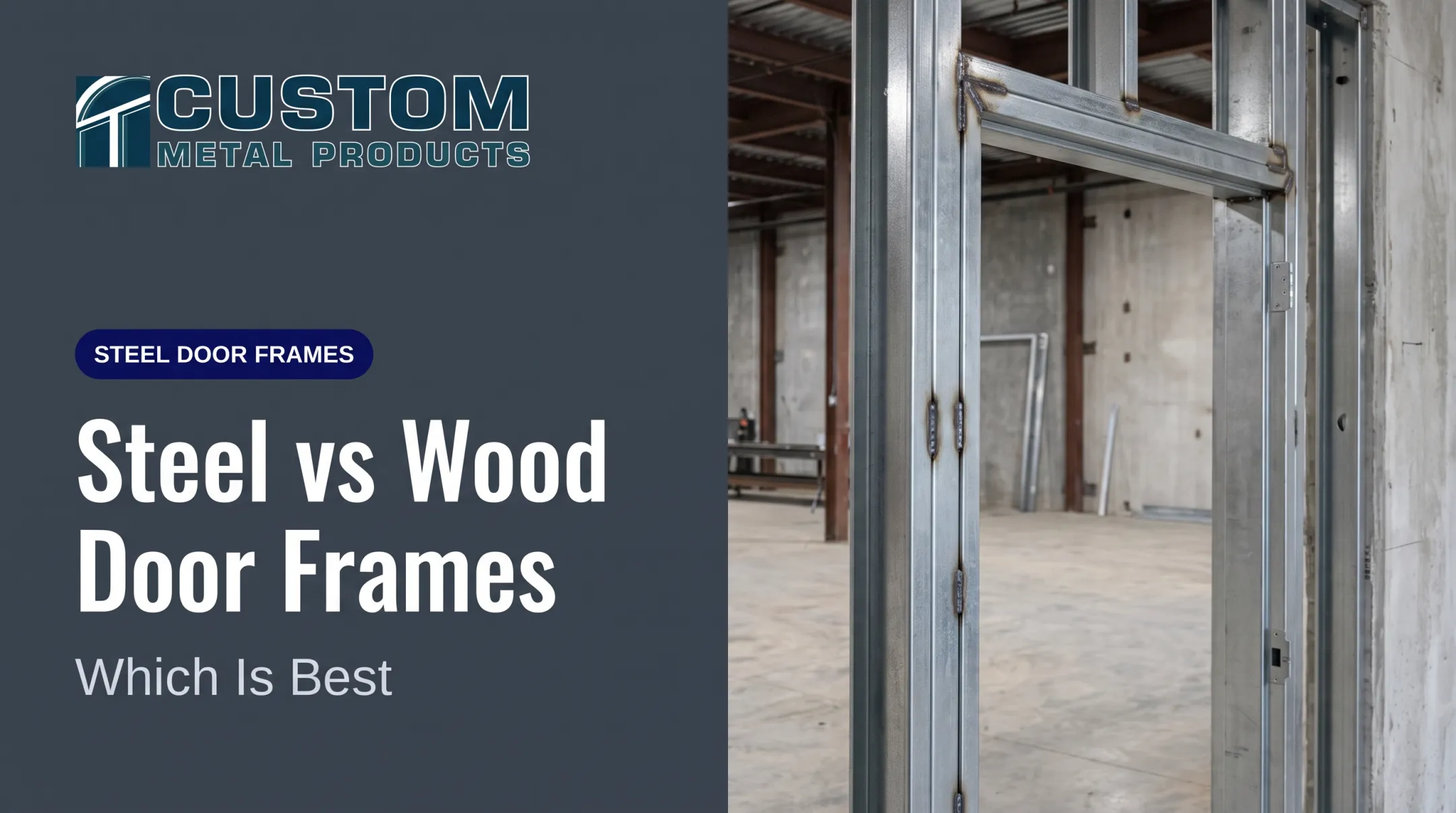
Windows, curtain walls, doors, hollow metal frames, jambs, heads, sills, and thresholds are where the wall's thermal, air, water, and fire-control layers all have to line up simultaneously. Miss the coordination here, and you've created a thermal bridge at exactly the location the code interpretation above flags as a linear bridge.
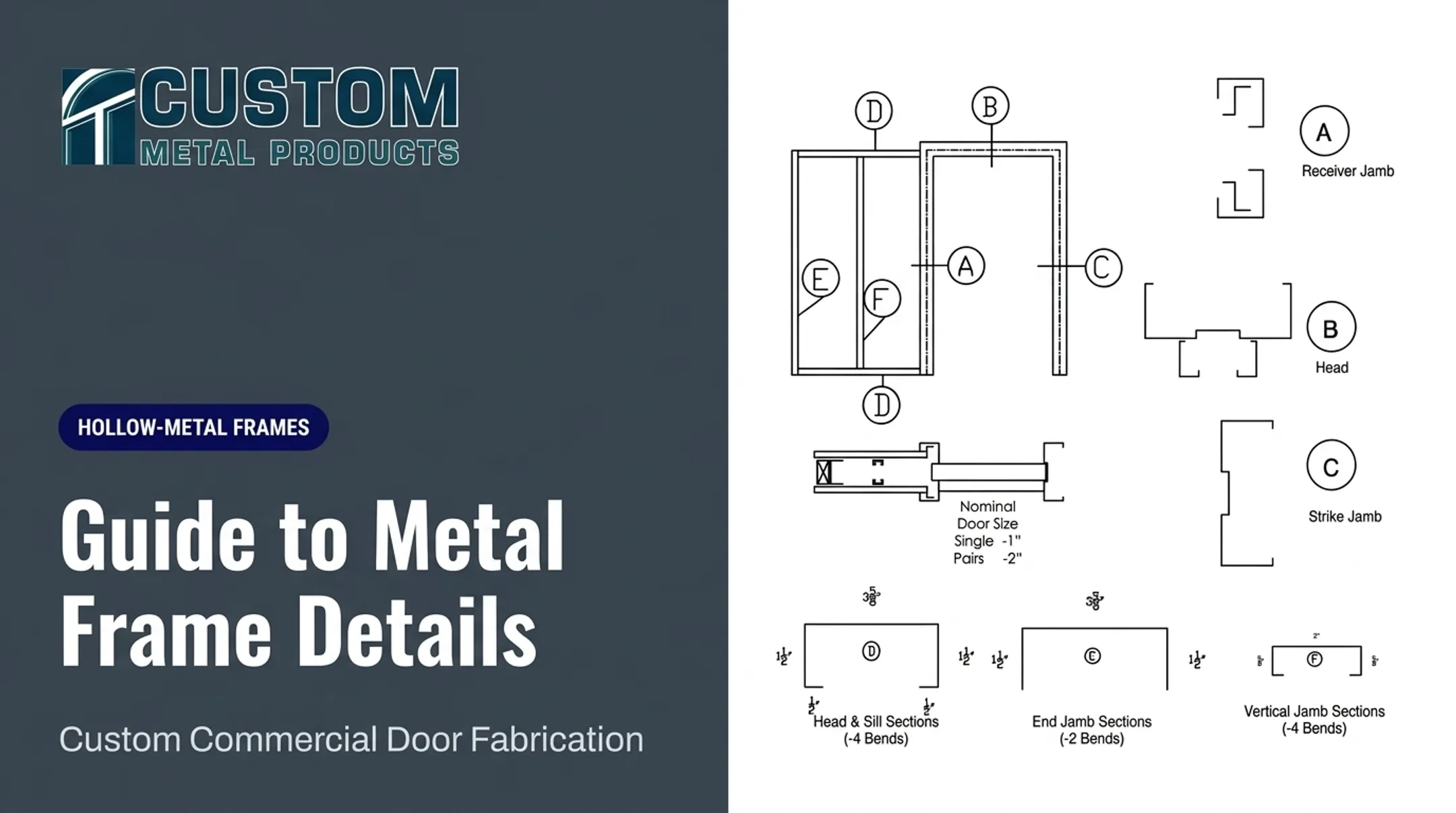
This is where hollow metal frame coordination matters. Custom Metal Products, a commercial hollow metal door and frame manufacturer based in Wilmington, North Carolina, works with architects and Division 8 teams on custom frame configurations, including arched, radius, and segmented profiles, along with UL-labeled fire-rated assemblies.
That is not a claim that every frame is thermally broken. It is a chance to coordinate frame and opening details with the project's thermal-break strategy early, rather than finding a mismatch after fabrication. Per NAAMM/HMMA 860-18, a thermally broken frame requires a continuous break specified for that project; no generic U-factor applies to standard frames across the board.
How to Specify, Install, and Verify Thermal Breaks
Getting thermal breaks right is a coordination problem before it's a product problem.
Start With Design Coordination
Identify thermal bridges during enclosure review, not after steel is ordered. Show the thermal-break location and continuity directly in drawings, and get architectural, structural, mechanical, fire-protection, and waterproofing input before fabrication begins.
Specify the Right Properties for Each Application
Depending on the application, your specification should address:
- Thermal resistance or conductivity
- Compressive and shear capacity
- Tension or moment demands, where applicable
- Dimensional tolerances
- Fire performance and moisture resistance
- UV exposure and service temperature
- Compatibility with adjacent materials
Structural Breaks Need Engineering, Not Just Insulation
A structural thermal break requires a full connection review: load paths, fastener behavior, deflection, bearing, slip resistance, corrosion protection, and the capacity of the surrounding steel or concrete. Manufacturer documentation on load-transfer roles (normal force, shear, moment) is a starting point, not a substitute for project-specific engineering.
One detail worth knowing: some thermal break plates are documented as not contributing to shear resistance, and the gap they introduce can bend bolts and reduce shear capacity depending on pack thickness. Get qualified engineering review rather than treat every insulating pad as structurally interchangeable.
Installation Controls
For enclosure applications:
- Maintain continuous coverage across the framing plane
- Seal joints and penetrations as required
- Preserve drainage planes
- Avoid compressing insulation beyond manufacturer limits
- Use compatible fasteners and tapes
For structural applications:
- Follow the manufacturer's approved detail exactly
- Maintain specified plate or module orientation and thickness
- Install correct bolts, washers, sleeves, and spacers
- Avoid field modifications that change the tested or engineered assembly
Verify Before You Cover It Up
Submittal review and product data checks come first. Beyond that, mockups, photographic documentation, visual inspections, and infrared thermography all have a role, and the right method depends on the project.
Infrared thermography, for example, offers qualitative guidance under ASTM standards. It flags anomalies but does not deliver a verified R-value on its own. Match the verification method to what the project must confirm.

Project Checklist: Questions to Resolve Before Ordering or Fabricating
Run through these before steel, frames, or cladding get fabricated:
- Where does steel cross the primary insulation layer? Check wall studs, headers, jambs, shelf angles, clips, balconies, roof supports, parapets, and service penetrations
- Is the solution a wall-assembly break, a structural connection break, or both? Identify who's documenting each requirement
- Do drawings and specs identify all performance criteria? Cover thermal, structural, fire, moisture, corrosion, and attachment requirements, plus approved manufacturers and acceptable substitutions
- Do doors, frames, glazing, cladding, flashings, and air/water barriers align? Confirm no gaps or unplanned conductive paths. Coordinate custom hollow metal frame details early, especially for unusual, fire-rated, or schedule-sensitive openings
- Have you verified current, locally adopted energy code provisions? Don't copy requirements from another climate zone or jurisdiction. The same IECC edition can carry different local amendments from one city to the next
On fire-rated openings, resolve labeling risk before fabrication. If a thermal-break detail or hardware choice keeps a fire-rated door or frame from qualifying for its intended label, the architect needs to know before work starts, not after. Confirm this wherever thermal and fire performance meet at the same opening.
Before cover-up, confirm:
- Continuity of the thermal break across the detail
- Joint treatment and sealing
- Penetration locations and treatment
- Fastener type and length
- Drainage path integrity
- Firestopping where required
- Corrosion protection
- Photographic records of the completed detail
Conclusion
Thermal breaks are a building-system strategy for controlling heat flow through steel, not insulation you add at the end. Steel conducts heat exceptionally well, so the break has to be designed into the assembly.
The decision rule is straightforward even when the details are not. Choose the solution based on:
- Where the thermal bridge occurs
- What thermal performance is required
- What structural loads the connection carries
- Which fire and moisture requirements apply
Then check that solution against the code pathway your jurisdiction has actually adopted.
Involve the architect, structural engineer, enclosure consultant, manufacturer, and installer early. Coordinating performance before steel, frames, cladding, and finishes are fabricated costs far less than fixing problems found in a mockup—or after occupancy.
Frequently Asked Questions
What are steel frame thermal breaks?
A thermal break is a low-conductivity interruption that cuts heat flow through steel without sacrificing structural or enclosure performance. It differs from cavity insulation, which fills space but does not stop conduction through the steel itself.
Can steel thermal break frames be knock-down?
Knock-down compatibility depends on the specific frame system, thermal-break detail, anchors, fasteners, and fire-rating requirements. Confirm the manufacturer's approved configuration for your project before ordering.
What materials are commonly used for thermal breaks in steel framing?
Common options include:
- Continuous rigid insulation
- Thermally improved clips or girts
- Insulating plates or pads
- Thermal washers or bushings
- Engineered structural modules
Choose based on loads, fire rating, moisture exposure, and the applicable building code.
Where should thermal breaks be installed in a steel-framed building?
Key locations include steel stud and roof assemblies, slab edges, balconies, canopies, parapets, shelf angles, rooftop supports, cladding attachments, and door or window interfaces. Each location needs project-specific evaluation rather than a one-size-fits-all detail.
Do thermal breaks replace continuous insulation in steel framing?
No. Thermal breaks and continuous insulation address related but different heat-flow paths. Most commercial assemblies need both, along with properly coordinated air, water, and vapor control layers.